ISO 6263 pdf download
ISO 6263 pdf download Hydraulic fluid power — Compensated flow-control valves — Mounting surfaces
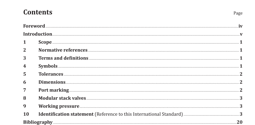
Scope
This International Standard specifies the dimensions and other data relating to surfaces on whichhydraulic compensated flow-control valves are mounted in order to ensure interchangeability.
lt applies to mounting surfaces for hydraulic compensated flow-control valves which represent currentpractice; they are generally applicable to industrial equipment.
2 Normative references
The following documents, in whole or in part, are normatively referenced in this document and areindispensable for its application. For dated references, only the edition cited applies. For undatedreferences, the latest edition of the referenced document (including any amendments) applies
ISO 1219-1, Fluid power systems and components – Graphical symbols and circuit diagrams — Part 1:Graphical symbols for conventional use and data-processing applications
ISO 1219-1, Fluid power systems and components — Graphical symbols and circuit diagrams — Part 1: Graphical symbols for conventional use and data-processing applications
ISO 3601-2:2008, Fluid power systems — O-rings — Part 2: Housing dimensions for general applications
ISO 4401, Hydraulic fluid power — Four-port directional control valves — Mounting surfaces
ISO 5598, Fluid power systems and components — Vocabulary
ISO 5783, Hydraulic fluid power — Code for identification of valve mounting surfaces and cartridge valve cavities
3 Terms and definitions
For the purposes of this document, the terms and definitions given in ISO 5598 and the graphical symbols given in ISO 1219-1 apply.
4 Symbols
4.1 For the purposes of this International Standard, the following symbols apply:
a) A, B, L, P, T, and V designate ports;
b) F 1 , F 2 , F 3 , and F 4 designate threaded holes for fixing screws;
c) G, G 1 , and G 2 designate the location of pin holes;
d) D designates the fixing screw diameter;
e) r max designates mounting surface edge radius.
4.2 The graphical symbols used in Tables 2, 4, 6, 8, 10, 12, 14, and 16 are in accordance with ISO 1219-1.
4.3 The code system used in this International Standard is defined in ISO 5783.
5 Tolerances
5.1 The following requirements shall be applied to the mounting surface, i.e. that area within the chain thick lines:
surface roughness: see ISO 3601-2:2008, 5.1.4 and 5.2.3;
surface flatness: 0,01 mm over a distance of 100 mm (see ISO 3601-2:2008, 5.1.4);
tolerance for diameters of locating pin holes: H12.
5.2 With respect to the origin, the following tolerances shall be complied with along x and y axes:
pin holes: ± 0,1 mm;
screw holes: ± 0,1 mm;
port holes: ± 0,2 mm.
For other dimensions, see the figures.
6 Dimensions
6.1 Mounting surface dimensions for hydraulic compensated flow-control valves shall be selected from the figures and tables specified in 6.2 to 6.9.
6.2 Mounting surface dimensions for compensated flow-control valves with main ports of 4,5 mm maximum port diameter (code: 6263-02-01-*-13) are given in Figure 1 and Table 1.
6.3 Mounting surface dimensions for compensated flow-control valves with main ports of 7,5 mm maximum port diameter (code: 6263-03-02-*-13) are given in Figure 2 and Table 3.
