ISO 3364 pdf download
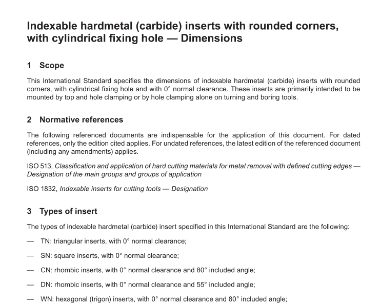
ISO 3364 pdf download Indexable hardmetal (carbide) inserts with rounded corners, with cylindrical fxing hole — Dimensions
1 Scope
This International Standard specifes the dimensions of indexable hardmetal (carbide) inserts with rounded corners, with cylindrical fxing hole and with 0° normal clearance. These inserts are primarily intended to be mounted by top and hole clamping or by hole clamping alone on turning and boring tools.
2 Normative references
The following referenced documents are indispensable for the application of this document. For dated references, only the edition cited applies. For undated references, the latest edition of the referenced document (including any amendments) applies.
ISO 513, Classifcation and application of hard cutting materials for metal removal with defned cutting edges — Designation of the main groups and groups of application
ISO 1832, Indexable inserts for cutting tools — Designation
3 Types of insert
The types of indexable hardmetal (carbide) insert specifed in this International Standard are the following:
— TN: triangular inserts, with 0° normal clearance;
— SN: square inserts, with 0° normal clearance;
— CN: rhombic inserts, with 0° normal clearance and 80° included angle;
— DN: rhombic inserts, with 0° normal clearance and 55° included angle;
— WN: hexagonal (trigon) inserts, with 0° normal clearance and 80° included angle;
— VN: rhombic inserts, with 0° normal clearance and 35° included angle.
Inserts covered by this International Standard are standardized with chip breakers on both faces, with chip breakers on one face only and with no ship breakers at all.
Neither the shape nor the dimensions of chip breakers are standardized. Thus, if necessary, special features shall be explained by means of a diagram or additional specifcations.
Table B.1 gives the range of sizes for these inserts.
4 Interchangeability
4.1 Tolerances
Indexable hard metal (carbide) inserts specifed in this International Standard are provided in tolerance classes in accordance with ISO 1832.
Other tolerances are given, either in Table 1 for hole dimensions, or in Tables 2 to 7 for insert dimensions.
4.2 Thickness, s, of inserts with chip breakers The thickness, s, of inserts with chip breakers is defned as the distance between the cutting edge at the corner and the opposing supporting surface of the insert; see Figure 1 a) and b) for inserts with chip breakers on one face only and Figure 1 c) for inserts with chip breakers on both faces.
5 Designation and marking
5.1 Designation
The designation of the indexable hardmetal (carbide) inserts complying with this International Standard shall conform to ISO 1832.
In addition to this designation, one or both of the following may be indicated:
— the symbol of the group of application, in accordance with ISO 513;
— the commercial designation of the hardmetal (carbide) grade.
