ISO 15500 pdf download
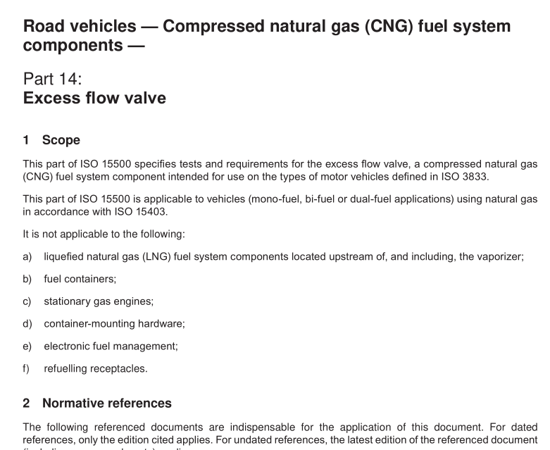
ISO 15500 pdf download Road vehicles — Compressed natural gas (CNG) fuel system components — Part 1 4: Excess fow valve
Scope
This part of ISO 15500 specifies tests and requirements for the excess flow valve, a compressed natural gasCNG) fuel system component intended for use on the types of motor vehicles defined in ISO 3833.
This part of ISO 15500 is applicable to vehicles (mono-fuel, bi-fuel or dual-fuel applications) using natural gasin accordance with ISO 15403.
It is not applicable to the following:
a) liquefed natural gas (LNG) fuel system components located upstream of, and including, the vaporizer;
b) fuel containers;
c) stationary gas engines;
d) container-mounting hardware;
e) electronic fuel management;
f) refuelling receptacles.
2 Normative referencesThe following referenced documents are indispensable for the application of this document, For datedreferences, only the edition cited applies. For undated references, the latest edition of the referenced document(including any amendments) applies.
ISO 15500-1,Road vehicles一 Compressed natural gas (CNG) fuel system components – Part 1: Generalrequirements and definitions
SO 15500-2, Road vehicles – Compressed natural gas (CNG) fuel system components – Part 2: Performanceand general test methods
3 Terms and definitions
For the purposes of this document, the terms and definitions given in ISO 15500-1 and the following apply.3.1
internal excess flow valveexcess flow valve installed inside the cylinder or cylinder valve
3.2
externalexcess flow valve
excess flow valve installed outside the cylinder or cylinder valve
3.4
fow-limiter type excess fow valve
excess fow valve that limits fow when activated
NOTE The device resets automatically when the excess fow condition is no longer present.
3.5
activation pressure
differential pressure fow or other condition specifed by the manufacturer at which the excess fow valve is activated
4 Marking
Marking of the component shall provide suffcient information to allow the following to be traced:
a) the manufacturer’s or agent’s name, trademark or symbol;
b) the model designation (part number);
c) the operating specifcations (working pressure, temperature range, excess fow valve type, activation fow or ΔP, maximum fow when activated).
The following additional markings are recommended:
— the direction of fow (when necessary for correct installation);
— the type of fuel;
— electrical ratings (if applicable);
— the symbol of the certifcation agency;
— the type approval number;
— the serial number or data code;
— reference to this part of ISO 15500.
NOTE This information can be provided by a suitable identifcation code on at least one part of the component when it consists of more than one part.
5 Construction and assembly
The excess fow valve shall comply with the applicable provisions of ISO 15500-1 and ISO 15500-2, and with the tests specifed in Clause 6 of this part of ISO 15500.
6 Tests
6.1 Applicability
