ISO 12996 pdf download
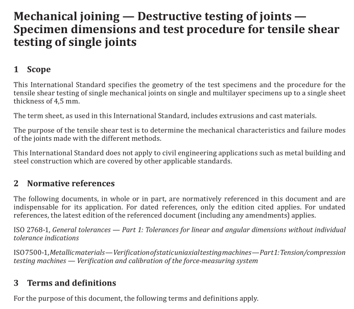
ISO 12996 pdf download Mechanical joining — Destructive testing of joints — Specimen dimensions and test procedure for tensile shear testing of single joints
Scope
This International Standard specifies the geometry of the test specimens and the procedure for thetensile shear testing of single mechanical joints on single and multilayer specimens up to a single sheetthickness of 4,5 mm.
The term sheet, as used in this International Standard, includes extrusions and cast materials.
The purpose of the tensile shear test is to determine the mechanical characteristics and failure modesofthe joints made with the different methods.
This International Standard does not apply to civil engineering applications such as metal building andsteel construction which are covered by other applicable standards.
2 Normative references
The following documents,in whole or in part, are normatively referenced in this document and areindispensable for its application, For dated references, only the edition cited applies. For undatedreferences, the latest edition of the referenced document (including any amendments) applies.
SO 2768-1, General tolerances — Part 1: Tolerances for linear and angular dimensions without individualtolerance indications
SO7500-1,Metallicmaterials–Verificationofstaticuniaxialtestingmachines-Part1:Tension/compressiontesting machines – Verification and calibration of the force-measuring system
3 Terms and definitions
For the purpose of this document, the following terms and definitions apply
31
tensile shear force
Fmax
maximum force recorded in the test
Note 1 to entry: lfrequired, further characteristic data,e.g. Fpo.2 (see 3.2),stiffness of the specimen c (see 3.7) orslope of the force curve, energy dissipation W (see 3.8 , can be determined according to the shear diagram givenin Figure 4.
3.2
elastic force limit
F
force where predetermined plastic or permanent displacement of the test specimen occurs
3.3
slippage force
F
force at which a relative movement of the joined parts is registered
3.4
displacement
s
change in the length of a specimen due to the application of a force
[SOURCE: ISO 18592:2009, 1 3.15 modified — symbol changed; “force” replaces “load”]
3.5
displacement at the tensile shear force F max
s F max
amount of displacement measured at tensile shear force F max
3.6
displacement at 0,3F max
s
F 0 3 ,
max
amount of displacement measured at 0,3F max
3.7
stiffness in elastic range
c
ratio of increase of force to the increase of elongation in the elastic range (c = ΔF/Δs)
3.8
dissipated energy
W
work or area under the force curve
3.9
dissipated energy up to F max
W F max
area under the force curve up to the point of maximum tensile shear force F max
