BS ISO 11093-7 pdf download
BS ISO 11093-7 pdf download Paper and board — Testing of cores Part 7: Determination of flexural modulus by the three-point method
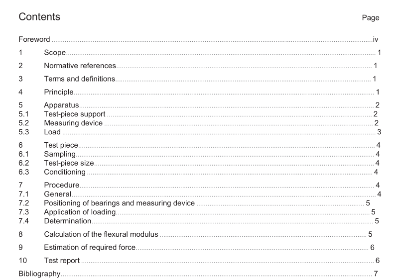
1 Scope
This part of lSO 11093 specifies a method for the determination, by the three-point method, of the flexuralmodulus of cylindrical paper and board cores which meet the following criteria:
-internal diameter:
50 mm to 350 mm;
-minimum wall thickness: 0,05 × internal diameter, but not less than 10,0 mm;
-minimum length of core:10 xinternal diameter, but not less than 1 000 mm.
lf the flexural modulus has to be used for the calculation of a paper core’s natural frequency, IS0 11093-8(2)applies instead of this lnternational Standard.
2Normative references
The following referenced documents are indispensable for the application of this document. For datedreferences, only the edition cited applies.For undated references, the latest edition of the referenced document(including any amendments) applies.
ISO 11093-1,Paper and board – Testing of cores — Part 1: Sampling
ISO 11093-3, Paper and board —Testing of cores —Part 3: Determination of moisture content using the ovendrying method
3Terms and definitions
For the purposes of this document, the following terms and definitions apply.
3.1
flexural modulusE
material property which, together with core dimensions, describes the resistance of the core to traction orbending deflection
4Principle
In order to determine the flexural modulus, a static bending test is conducted on the test piece.The test pieceis considered as a “beam”and the classic beam theory for the deflection of “slender beams” is applied. Duringthe test, the test piece is supported at its ends and loaded transversally by a load applied by a hanging weight.Special measures are undertaken to avoid permanent deformation of the test piece and to ensure the validityof the equation, used for calculation.
The flexural modulus is calculated as described in Clause 8.
5 Apparatus
5.1 Test-piece support The test piece is supported at each end by two rolls arranged like a vee, referred to as the lower bearings (see Figure 1). The angle between the two rolls shall be 120° ± 2°. The diameter a of the rolls shall be (30 ± 1) mm. The width b shall be large enough to allow the test piece to rest on the lateral surface area of the rolls. At an angle of 120°, the theoretical minimum value of b is half the outer diameter D of the core.
5.2 Measuring device The measuring device consists of two rolls arranged like a vee, referred to as the upper bearings, a support bar on which the upper bearings are mounted, and a displacement gauge. The lower and upper bearings are arranged with mirror-image symmetry.
The measuring device is placed on the test piece. The change in deflection f of the test piece is measured in the direction of the applied force using a displacement gauge (see Figure 2).
If a material-testing machine is used to apply the load (see 5.3), it may also be used to measure the deflection of the test piece. It shall be accurate to ±0,01 mm.
The tolerances of the distances and the force F are defined in Clause 7.
