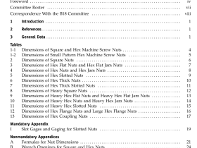
ASME B18.2.2 pdf download
ASME B18.2.2 pdf download Nuts for General Applications: Machine Screw Nuts, Hex, Square, Hex Flange, and Coupling Nuts (Inch Series) 3.2 Corner Fill A rounding or lack of fill at junction of hex corners with chamfer shall be permissible, provided the width across corners is within specified limits at and beyond a distance equal to 17.5% of the basic thread...
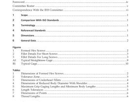
ASME B18.2.3.2 pdf download
ASME B18.2.3.2 pdf download Metric Formed Hex Screws 6.6.5 Position of Body-to-Thread. For products with cut threads, at maximum material condition, the axis of the screw body, D s (derived median line), over a length equal to the nominal screw diameter from the last scratch of thread, shall be within the positional tol- erance zone diameter specified in Table 2...
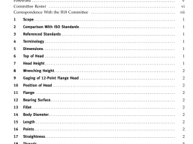
ASME B18.2.5M pdf download
ASME B18.2.5M pdf download Metric 12-Point Flange Screws 8 WRENCHING HEIGHT Corners of the 12 points shall be fully formed and reasonably uniform over the wrenching height, K w . Head drive root radius, R 4 , applies to the entire length of the wrenching height, K w (see Table 1). 9 GAGING OF 12-POINT FLANGE HEAD The head shall...
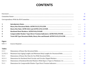
ASME B18.2.6 pdf download
ASME B18.2.6 pdf download Fasteners for Use in Structural Applications 1INTRODUCTORY NOTES 1.1 Scope 1.1.1 This Standard covers the complete general and dimensional data for five products in the inch series recognized asan American National Standard.These five structural products include(a) heavy hex structural bolts: ASTM F3125/F3125M(b)heavy hex nuts: ASTM A563 and ASTM A194/A194M(c) hardened steel washers – circular, circular clipped,...
ASME B18.2.9 pdf download
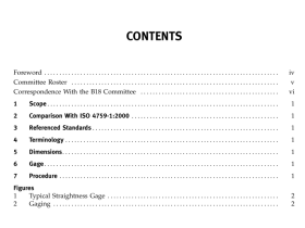
ASME B18.2.9 pdf download Straightness Gage and Gaging for Bolts and Screws 1 SCOPE This Standard describes a gage and procedure forchecking bolt or screw straightness at maximum material condition (MMC). 2 COMPARISON WITHISO 4759-1:2000 This Standard uses an adjustable gage, instead of plainsleeve gages like the example shown in ISO 4759-1Annex C, Figure C.24. The adjustable gage avoids thenecessity...
ASME B18.3 pdf download
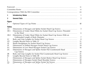
ASME B18.3 pdf download Socket Cap, Shoulder, and Set Screws, Hex and Spline Keys (Inch Series) 1 INTRODUCTORY NOTES 1.1 Scope 1.1.1 This Standard covers complete general and dimensional data for various types of hexagon and spline (fluted) socket cap screws, shoulder screws, set screws, and hexagon and spline keys recognized as an American National Standard. Also, included are appen-...
ASME B18.5 pdf download
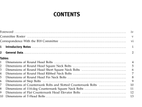
ASME B18.5 pdf download Round Head Bolts (Inch Series) 1 INTRODUCTORY NOTES 1.1 Scope 1.1.1 This Standard covers the complete general and dimensional data for the various types of inch series bolts generally classified as round head bolts and recog- nized as American National Standard. 1.1.2 The inclusion of dimensional data in this Standard is notintended to imply that all...
ASME B18.6.2 pdf download
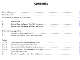
ASME B18.6.2 pdf download Square Head Set Screws and Slotted Headless Set Screws (Inch Series) 2.1.3 Head True Position. The axis ofthe head shall be located at true position within a tolerance zone having a diameter equal to 6% of the specified maximum width across flats of the head, relative to the axis of the screw shank, regardless of feature...
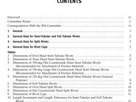
ASME B18.7 pdf download
ASME B18.7 pdf download General Purpose Semi-Tubular Rivets, Full Tubular Rivets, Split Rivets, and End Caps 2 GENERAL DATA FOR SEMI-TUBULAR AND FULL TUBULAR RIVETS 2.1 Heads 2.1.1 Because the heads of these rivets are not machined or trimmed, the circumference may be some- what irregular and edges may be rounded or flat. 2.1.2 The bearing surface of oval and...
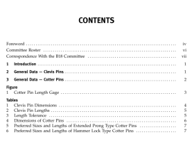
ASME B18.8.1 pdf download
ASME B18.8.1 pdf download Clevis Pins and Cotter Pins (Inch Series) 2.2.3 Clevis Pin Head Periphery. The periphery of the head shall be within a circular runout equal to 12% of the maximum head diameter or 0.020 in., whichever is greater, with respect to the axis of the shank, as deter- mined over a length under the head equal to...