ASME B89.1.6 pdf download
ASME B89.1.6 pdf download MEASUREMENT OF PLAINIM TERNAL DIAMETERSFOR USE AS MASTERRINGS UR RING GAGES
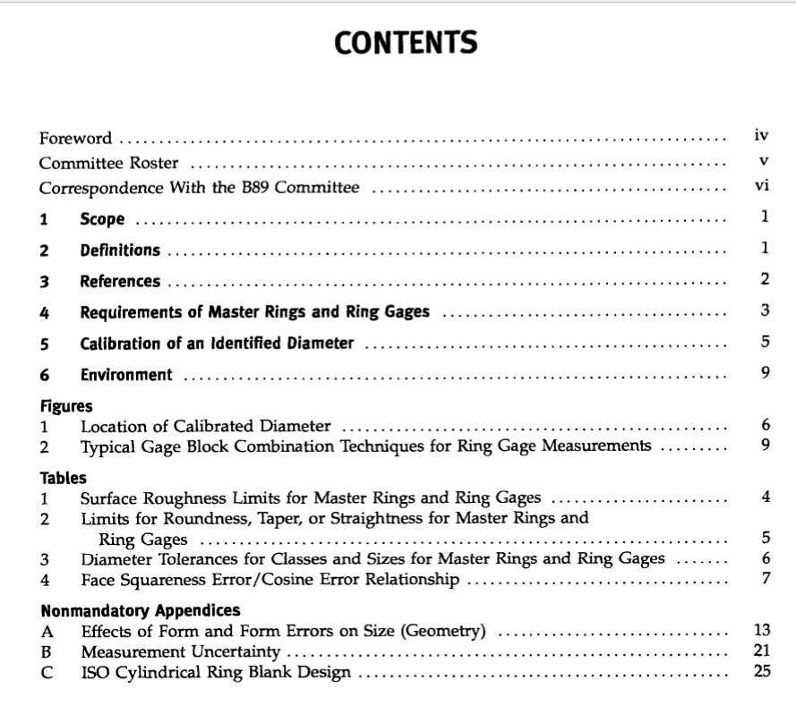
REQUIREMENTS OF MASTER RINGS AND RING GAGES
4.1 General
The capability of measuring equipment and tech-niques to achieve a high order of precision in the calibra-tion of master rings or ring gage is limited by relevantfeatures and conditions of the gage to be measured.These are discussed in the following sections:
(a)4.2 Design
(b)4.3 Material
(c)4.4 Surface Roughness
(d)4.5 Geometric Requirements
(e)4.6 Face Perpendicularity of Rings
(f)4.7 Tolerance Classes
All dimensions and specifications given in this Stan-dard are for gages that have not been modified.Modifi-cations to gages through processes such as machining,grinding, stamping,etc., where heat or stress is producedcan alter the measured diameter(s). and thus wouldinvalidate a reported dimension from a measurementtaken before the modification.
The minimum marking requirements for ring gagesshall be the size or diameter, and tolerance class. if thetolerance does not match one of the standard classes aslisted in Tables 1,2, and 3 it does not have to be included.For rings made to tolerances other than those listed, thecustomer should specify the marking requirements.
4.2 Design
The design and proportion specifications for gageblanks are given in ANSI/ ASME B47.1.
The Iso design is acceptable when communicatedbetween the customer and the manufacturer. See Appen-dix C for ISo 3670 design specifications.
4.3 Material
The material, including coatings or wear inserts,of rings or ring gage blanks shall be free from inclusionsor other imperfections, which would affect surface tex-ture. It is desirable for the material to have approxi-mately the same coefficient of expansion as the gageblocks to be used in order to minimize the effect of smalldifferences in temperature.It shall respond to applicablehardening and stabilizing processes to permit finishingto the pertinent surface roughness and to assure dimen-sional stability. Finished surfaces should have a mini-mum hardness equivalent to 60 on the Rockwell C Scale.Master gages shall not be subjected to any quick agingor shock treatment as a check of stability. if the materialshows magnetism, the gage should be de-magnetizedbefore measurements are taken.
4.4 Surface Roughness
The surface roughness shall be consistent with theclass tolerance of the gage. ‘Table 1 lists maximumroughness values expressed in arithmetic average (Ra)roughness values. ASME B46.1, shall be consulted forreference information.
4.5 Geometric Requirements
4.5.1 General.The diameter will be measured persection 6 of this Standard.Typical acceptance criteriafor geometric requirements are diameter measurementsspaced approximately 90 deg apart in each of threeplanes: the midsection, and each end, located 36 in.(1.6mm) from inside the ends of corner radii or chamfers. Forsizes below 0.150 in. (3.8 mm), a total of four diametermeasurements should be taken in two planes within thecenter half of the ring.
