ASME B18.2.1 pdf download
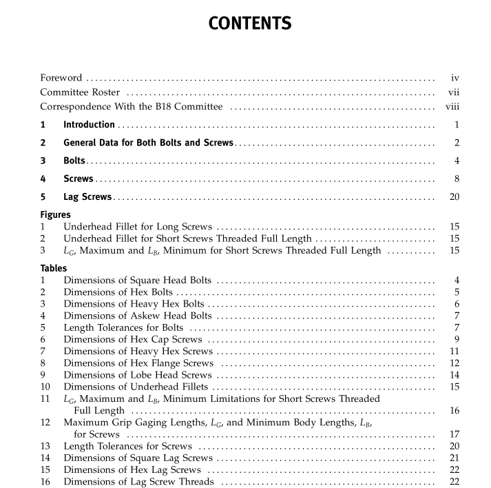
ASME B18.2.1 pdf download Square, Hex, Heavy Hex, and Askew Head Bolts and Hex, Heavy Hex, Hex Flange, Lobed Head, and Lag Screws (Inch Series)
2 GENERAL DATA FOR BOTH BOLTS AND SCREWS
2.1 Heads
2.1.1 Top of Head. Top of head shall be full form and chamfered, withthe diameterofchamfercircle equal to the maximum width across flats, on square or hex head products and the “B” dimension shown in Table 11 for lobed head screws with a tolerance of −15%.
2.1.2 Width Across Flats. The width across flats of head shall be the overall distance measured perpendicu- lar to the axis of product between two opposite sides of the head in accordance with the notes in respective dimensional tables.
2.1.3 Head Height. The head height shall be the overall distance measured parallel to the axis of product from the top of the head to the bearing surface and shall include the thickness ofthe washer face where provided.
2.1.4 Position of Head. The runout of the flats or lobes of the head shall be no greater than 6% of the maximum width across flats or lobes. For reference pur- poses, the evaluation shall be made by indicating on the flats or outer surface of lobes while holding the body one bolt diameter from under the head and rotating the part.
2.2 Bolt or Screw Length The bolt or screw length shall be the distance mea- sured parallel to the axis of product from the bearing surface of the head to the extreme end of the bolt or screw, including the point if the product is pointed.
2.3 Body Diameter The body diameter minimum/maximum limits are defined in each of the respective applicable tables. Unless otherwise specified by the purchaser, the body style supplied shall be full-size body.
NOTES:
(1) Only bolts and lag screws are permitted to have die seams on their body that exceed the body diameter. Die seams on the body and all other styles ofscrews that exceed the body diame- ter are not permitted.
(2) For recommended clearance of hole sizes for bolts and screws, refer to ASME B18.2.8.
2.4 Points Unless otherwise specified, bolts need not be pointed. Products designated as screws, with the exception of lag screws, are required to have a chamfered point. The chamfer angle may vary depending on the manufacturing process. When specified, the chamfer angle should be considered a reference dimension only. The presence of a point is to reduce the possibility of damage to the leading threads and promote assembleability with a tapped hole or nut. Point features not defined in a given product standard are at the discretion of the manufacturer.
