ASME B16.20 pdf download
ASME B16.20 pdf download Metallic Gaskets for Pipe Flanges Ring-Joint, Spiral-Wound, and Jacketed
2.7 Identification Number
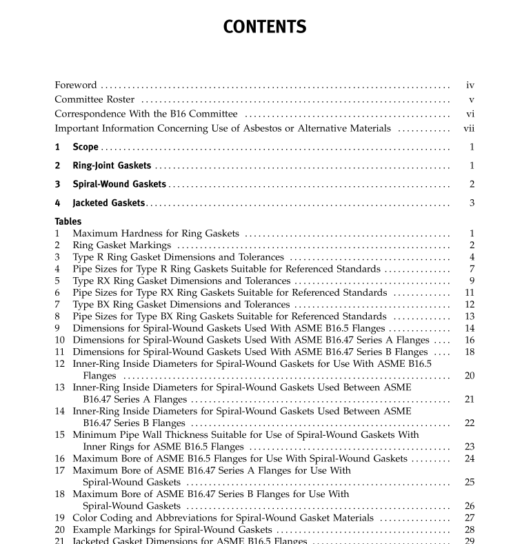
Dimensional reference identification numbers areassigned to ring-joint gaskets and are shown in Tables 3through 8 (Tables I-1, I-2, and I-3 of Mandatory Appendix I).
3 SPIRAL-WOUND GASKETS
3.1 Size and Class
Spiral-wound gaskets, including centering ring andinner ring (paras. 3.2.4 and 3.2.5), are identified by flangesize (NPS),pressure class, and the appropriate flangestandard (ASME B165 or ASME B16.47).
3.2 Dimensions and Tolerances
3.21 General, Dimensions and tolerances for spi-ral-wound gaskets, centering rings, and inner rings shallbe in accordance with Tables 9 through 14 (Tables I-4through I-9 of Mandatory Appendix I) and as specifiedin this section.
3.2.2 Construction.Spiral-wound gaskets shall beconstructed as alternate plies (circular layers counted asrevolutions) of preformed metal windings and pliantfillers that are spirally wound. For the finished gasket,the filler shall be essentially flush with, but not below,the metal winding on both contact faces of the gasket.The metal strip in the winding shall be 0.15 mm(0.006 in.) to 0.23 mm (0.009 in) thick. The filler materialthickness shall be determined by the manufacturer.
3.2.3 MetalJoining. The inner windings shall have aminimum of three plies of preformed metal strip withoutfiller. The initial two plies shall have spot welds spaced around the inner circumference. The minimum numberof welds shall be three. The maximum distance betweenwelds shall be 76 mm (3.0 in.). The outer windingswhich shall have a minimum of three plies of preformedmetal without filler, shall be spot-welded circumferen-tially with a minimum of three welds, the last of whichshall be the terminal weld.
The distance of the first weld from the terminal weldshall be no greater than 38 mm (1.5 in.). Up to fouradditional loose preformed metal windings beyond theterminal weld may be used to retain the gasket into thecentering ring.
324 Centering Ring. All spiral-wound gasketsshall be furnished assembled into a centering ring. Thecentering ring thickness shall be from 2.97 mm (0.117 in.)to 3.33 mm (0.131 in.) and suitably grooved on the insidediameter so as to retain the gasket.
3.2.5 Inner Ring.Inward buckling of spiral-woundgaskets has been identified as a potential problem. Innelrings shall be furnished with all spiral-wound gasketshaving PTFE (polytetrafluoroethylene) filler material.Inner rings for flexible graphite-filled spiral-wound gaskets shall be furnished unless the purchaser specifiesotherwise.
For all filler materials, inner rings shall be furnishedin spiral-wound gaskets for
(a) NPS 24 and larger in Class 900
(b) NPS 12 and larger in Class 1500
(c) NPS 4 and larger in Class 2500
Inner rings are required for these gaskets due to highavailable bolt loads, which may result in outer ringdamage.
The inner ring thickness shall be from 2.97 mm to3.33 mm (0.117 in.to 0131 in.).
Tables 12 through 14 (Tables I-7 through I-9 of Mandatory Appendix I) show inner ring inside diameters thatmay extend a maximum of 1.5 mm (0.06 in.) into theflange bore under the worst combination of flange boreeccentric installation, and tolerance.
Gaskets with inner rings should be used only withsocket welding,lapped,welding neck, and integralflanges. Reference Table 15 for minimum pipe wall thick-ness for use with gaskets with inner rings. ReferenceTables 16,17,and 18 (Tables I-10 and I-11 of MandatoryAppendix I) for maximum allowable bore for use with
