ISO 21940 pdf download
ISO 21940 pdf download Mechanical vibration — Rotor balancing — Part 1 4: Procedures for assessing balance errors
1 Scope
This part of ISO 21940 specifes the requirements for the following:
a) identifying errors in the unbalance measuring process of a rotor;
b) assessing the identifed errors;
c) taking the errors into account.
This part of ISO 21940 specifes balance acceptance criteria, in terms of residual unbalance, for both directly after balancing and for a subsequent check of the balance quality by the user.
For the main typical errors, this part of ISO 21940 lists methods for their reduction in an informative annex.
2 Normative references
The following referenced documents are indispensable for the application of this document. For dated references, only the edition cited applies. For undated references, the latest edition of the referenced document (including any amendments) applies.
ISO 1925, Mechanical vibration — Balancing — Vocabulary 11)
ISO 1940-1, Mechanical vibration — Balance quality requirements for rotors in a constant (rigid) state — Part 1:Specifcation and verifcation of balance tolerances 12)
ISO 11342, Mechanical vibration — Methods and criteria for the mechanical balancing of fexible rotors 13)
ISO 21940-21, Mechanical vibration — Rotor balancing — Part 21: Description and evaluation of balancing machines
3 Terms and defnitions
For the purposes of this document, the terms and defnitions given in ISO 1925 apply.
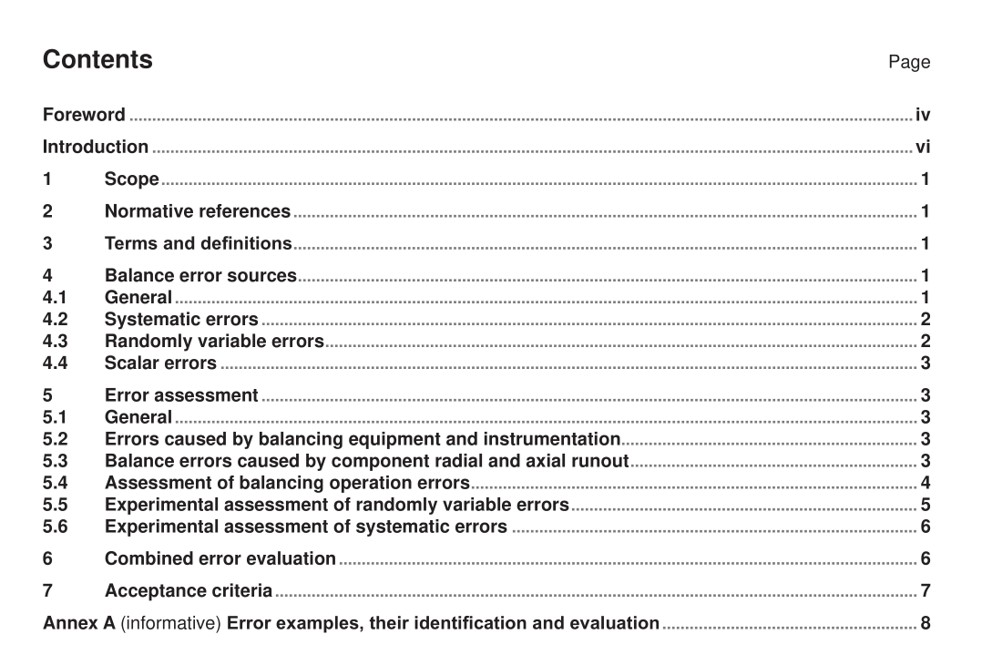
4 Balance error sources
4.1 General
Balancing machine balance errors can be classifed into:
a) systematic errors, in which the magnitude and angle can be evaluated either by calculation or measurement;
b) randomly variable errors, in which the magnitude and angle vary in an unpredictable manner over a number of measurements carried out under the same conditions;
) scalar errors, in which the maximum magnitude can be evaluated or estimated, but its angle is indeterminate.
Depending on the manufacturing processes used, the same error can be placed in one or more categories.
Examples of error sources which may occur are listed in 4.2, 4.3, and 4.4.
Some of these errors are discussed in greater detail in Annex A.
4.2 Systematic errors
Examples of balancing machine systematic error sources are:
a) inherent unbalance in the drive shaft;
b) inherent unbalance in the mandrel;
c) radial and axial runout of the drive element on the rotor shaft axis;
d) radial and axial runout in the ft between the component to be balanced or in the balancing machine
mandrel (see 5.3);
e) lack of concentricity between the journals and support surfaces used for balancing;
f) radial and axial runout of rolling element bearings which are not the service bearings and which are used to support the rotor;
g) radial and axial runout of rotating races (and their tracks) of rolling element service bearings ftted after balancing;
h) unbalance due to keys and keyways;
i) residual magnetism in the rotor or mandrel;
j) reassembly errors;
k) balancing equipment and instrumentation errors;
l) differences between service shaft and balancing mandrel diameters;
m) universal joint defects;
n) temporary bend in the rotor during balancing;
o) permanent bend in the rotor after balancing.
4.3 Randomly variable errors
Examples of balancing machine randomly variable error sources are:
a) loose parts;
b) entrapped liquids or solids;
c) distortion caused by thermal effects;
d) windage effects;
e) use of a loose coupling as a drive element;
f) transient bend in the horizontal rotor caused by gravitational effects when the rotor is stationary.
