BS EN ISO 19953 pdf download
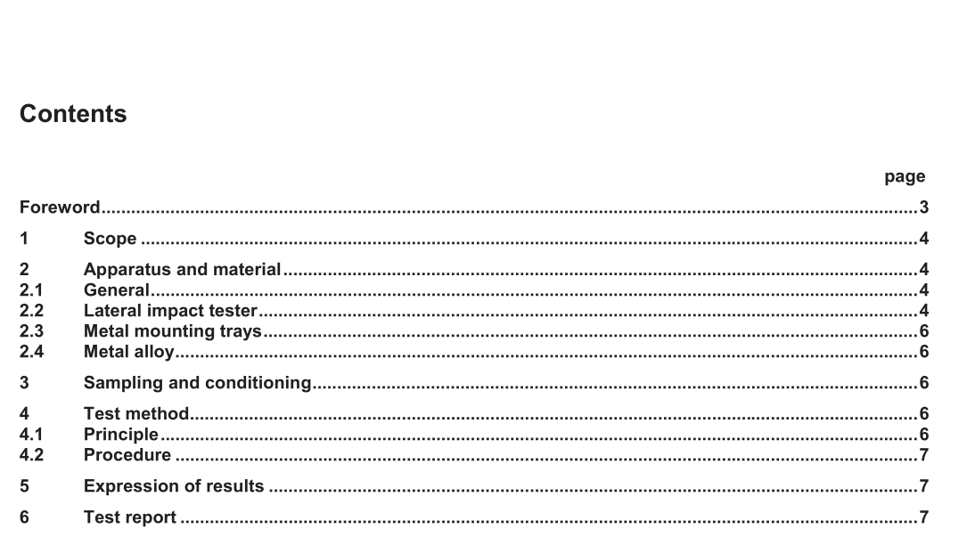
BS EN ISO 19953 pdf download Footwear — Test methods for heels — Resistance to lateral impact
2.4 Metal alloy Melting point between 100° C and 150° C.
3 Sampling and conditioning
3.1 Take free heels and set each heel in a dry metal mounting tray (3.2), using the procedure described in 3.2 or, for very short heel (usually those below 40 mm in height), the procedure described in 3.3, to obtain a test specimen assembly.
3.2 Place the heel centrally in the tray so that the seat breast edge is against a flat end of the tray and the heel tip points upwards (see Figure 2). Heat the metal alloy (3.3) until it is at the lowest temperature at which it will flow into all parts of the tray, filling the space around the heel to within 3 mm from the top. Allow the alloy to cool and set thereby providing a rigid mounting for the heel.
3.3 Since some very short heels cannot be struck correctly by the striker if mounted in accordance with 4.2 (because the bottom of the pendulum catches the base clump assembly), a different method of mounting is necessary. In such cases mount the heel with the rear of the heel seat against a flat end of the tray. Cut a small amount from the rear of the heel so as to set the heel further towards the rear of the mounting tray if this allows the striker to strike the heel correctly.
4 Test method
4.1 Principle A heel, clamped with the tip uppermost and the stem approximately vertical, is subjected repeatedly to measured blows from a pendulum striker, the energy of the blows increasing successively until the heel fails.
4.2 Procedure
4.2.1 Position the test specimen assembly in the lateral impact tester (2.2) sliding the assembly up the inclined plane of the base clamp (2.1.5) as far as possible and locking into position with the back of the heel facing the pendulum. Set the test specimen assembly at a suitable angle to the horizontal so that the blow will be applied at right angles to the heel stem. Adjust the clamp so that the heel just contacts the striker when the pendulum is vertical, with the tip of the heel 6 mm above the striker tip.
4.2.2 Lift the pendulum to the 0,68 J position and release, so that the striker (2.1.3) falls against the heel stem. Catch the pendulum on its rebound to prevent a second blow. Repeat this procedure, increasing the impact energy at each blow by 0,68 J either until the heel stem breaks, until it bends and the pendulum jams, or until an impact energy of 18,3 J has been applied. Record total number of blows delivered.
4.2.3 Damage involving fracture or cracking of the heel at the point of impact of the striker is regarded as invalid in this test, since it is due to the effect of the striker acting as a chisel rather than fracture of the heel due to impact of the heel as in wear. If such damage occurs, report it together with this explanation.
