BS ISO 10110-10 pdf download
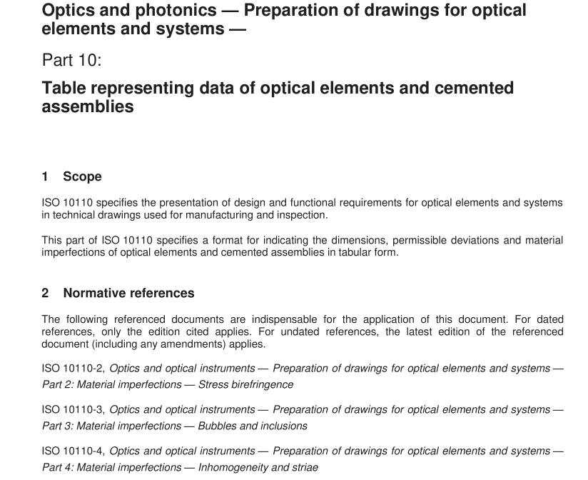
BS ISO 10110-10 pdf download Optics and photonics — Preparation of drawings for optical elements and systems — Part 10: Table representing data of optical elements and cemented assemblies
Scope
ISO 10110 specifies the presentation of design and functional requirements for optical elements and systemsin technical drawings used for manufacturing and inspection.
This part of ISO 10110 specifies a format for indicating the dimensions, permissible deviations and materiaimperfections of optical elements and cemented assemblies in tabular form.
2Normative references
The following referenced documents are indispensable for the application of this document. For datedreferences, only the edition cited applies. For undated references, the latest edition of the referenceddocument (including any amendments) applies.
ISO 10110-2,Optics and optical instruments — Preparation of drawings for optical elements and systems -Part 2: Material imperfections — Stress birefringence
ISO 10110-3,Optics and optical instruments — Preparation of drawings for optical elements and systems -Part 3: Material imperfections – Bubbles and inclusions
ISO 10110-4,Optics and optical instruments — Preparation of drawings for optical elements and systems -Part 4: Material imperfections – Inhomogeneity and striae
ISO 10110-5,Optics and optical instruments — Preparation of drawings for optical elements and systems -Part 5: Surface form tolerances
ISO 10110-6,Optics and optical instruments — Preparation of drawings for optical elements and systems -Part 6: Centring tolerances
SO 10110-7, Optics and optical instruments — Preparation of drawings for optical elements and systems -Part 7: Surface imperfections tolerances
ISO 10110-8,Optics and optical instruments — Preparation of drawings for optical elements and systems -Part 8: Surface texture
ISO 10110-9,Optics and optical instruments — Preparation of drawings for optical elements and systems -Part 9: Surface treatment and coating
ISO 10110-11, Optics and optical instruments — Preparation of drawings for optical elements and systems -Part 11: Non-toleranced data
ISO 10110-17, Optics and photonics — Preparation of drawings for optical elements and systems — Part 17Laser irradiation damage threshold
3 Format
3.1General
The drawing shall consist of the following three fields (see Figures 1 and 2):
drawing field in accordance with 3.2:
table field in accordance with 3.3:
title field in accordance with 3.4
3.2 Drawing field
In this field, a schematic drawing of the optical element or cemented assembly shall be given, together with allinformation not given in the table field. lt is not necessary that the drawing be true-to-scale; if a drawing scalefactor is indicated, the drawing shall be a true-to-scale technical drawing.
The datum axis for centring and the surface texture specification (see lSO 10110-6 and 1SO 10110-8) shall beindicated on the drawing.
3.3 Table field
This field contains dimensions, tolerances, and permissible material imperfections of the optical element orcemented assembly.It is sub-divided into subfields.
The number and contents of the subfields depend on whether a single element or a cemented assembly isspecified.
a) In the case of a single element:
the left subfield refers to the left surface (surface 1) of the optical element;
the central subfield refers to material specification;
the right subfield refers to the right surface (surface 2) of the optical element.
See Figures 3 and 4.
b) In the case of a cemented assembly:
the number of subfields equals the number of surface;cemented or contacted surfaces are counted as one surface
See Figures 5, 6 and 7.
