IEC 61883-3 pdf download
IEC 61883-3 pdf download Consumer audio/video equipment – Digital interface – Part 3: HD-DVCR data transmission
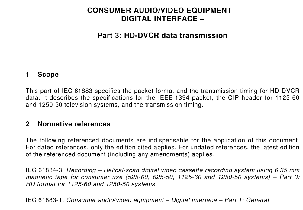
1Scope
This part of lEC 61883 specifies the packet format and the transmission timing for HD-DVCRdata. lt describes the specifications for the lEEE 1394 packet, the ClP header for 1125-60and 1250-50 television systems, and the transmission timing.
2Normative references
The following referenced documents are indispensable for the application of this document.For dated references,only the edition cited applies.For undated references, the latest editionof the referenced document (including any amendments) applies.
IEC 61834-3,Recording – Helical-scan digital video cassette recording system using 6,35 mmmagnetic tape for consumer use (525-60,625-50,1125-60 and 1250-50 systems) – Part 3:HDformat for 1125-60 and 1250-50 systems
IEC 61883-1,Consumer audio/video equipment – Digital interface – Part 1 : General
IEC 61883-2,Consumer audiolvideo equipment – Digital interface – Part 2: SD-DVCR datatransmission
3Abbreviations
For the purpose of this document, the following abbreviations apply:
1125-60 system:the 1125-line system with a frame frequency of 30,00 Hz1250-50 system:the 1250-line system with a frame frequency of 25,00 HzHD-DVCR:
high-definition digital video cassette recorder
IEEE 1394 packet: IEEE 1394 isochronous packet defined in lEC 61883-1
4Construction of IEEE 1394 packet
4.1Source packet structure of the HD-DVCR data stream
For the HD-DVCR data stream, the data structure for digital interface defined in lEC 61834-3,Clause 10 is used.The source packet size for the HD-DvCR data stream is 960 bytes, dividedinto 12 DIF blocks.
The correspondence between DlF blocks and source packets for the 1125-60 system andthe 1250-50 system are shown in Figure 1 and Figure 2 respectively.
4.2 Packetization of source packet of the HD-DVCR data stream
A source packet shall not be divided and shall be equal to a data block.
Data blocks transmitted in an IEEE 1 394 isochronous cycle shall be determined according to the TR value in the CIP header (see 5.2). An empty packet is placed in any cycle with no data block.
Where the TR value is
00 2 (1 x), one or no data block is transmitted;
01 2 (2x), two or no data block are transmitted;
1 0 2 (4x), four or no data block are transmitted.
The SYT field of the CIP header (see 5.1 ) is used to synchronize the transmitter and the receiver.
4.3 Transmission order of video frames for high-speed transmission
Transmission order of data within one video frame is defined in Figure 1 and Figure 2. For high-speed transmission, the transmission order of each video frame data shall follow the time sequence.
5 CIP header
5.1 CIP header for HD-DVCR data stream
The structure of the CIP header for the HD-DVCR data stream is the same as the structure of the CIP header for the SD-DVCR data stream (see IEC 61 883-2, 5.1 ).
The DBS for HD takes different values from that for SD through the difference of data block size as given in 4.1 .
5.2 FDF area
The STYPE takes different values as shown in Table 1 of IEC 61 883-2.
Where the STYPE is 0001 0 2 , TR is defined as follows.
